
Why Liquid Cooling Is Becoming Core AI Data-Center Infrastructure
Editorial note: Some links in this article are affiliate links — we may earn a commission if you sign up, at no extra cost to you. Research guides are distinguished from documented firsthand reviews in our editorial standards. Read our editorial standards →
Why Liquid Cooling Is Becoming Core AI Data-Center Infrastructure
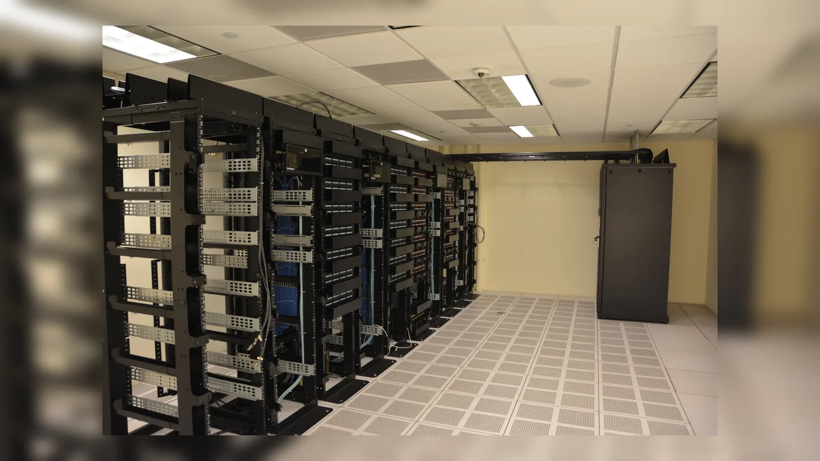
Hero photo attribution: Datacenter Server Racks, via Wikimedia Commons.
The important change in AI infrastructure is not that data centers have discovered water. Liquid has cooled specialist computers for decades. The change is that accelerated-computing clusters are making it difficult to treat liquid cooling as an exotic add-on. When a rack contains tightly packed GPUs, high-speed networking, power conversion and memory, the heat is concentrated in places that room air must reach through a succession of heat sinks and fans. That architecture can be both electrically expensive and physically limiting.
Reported fact: NVIDIA’s current rack-scale systems describe liquid-cooled compute and networking configurations, while the Open Compute Project (OCP) publishes requirements intended to make advanced liquid cooling deployable across facilities. Those are product and industry-design signals, not proof that every AI installation needs the same loop. Inference: liquid cooling is becoming core infrastructure because it removes a constraint on rack design, rather than merely improving a utility bill. That distinction matters to buyers: the business case is usually about usable compute density, delivery schedule and reliability as much as cooling energy.
The heat problem is moving inside the rack
Traditional raised-floor and perimeter-cooling designs were built around servers whose heat could be collected by moving large volumes of air. Air is safe, familiar and easy to distribute, but its volumetric heat capacity is modest. Raising fan speed and supply-air volume can extend an air-cooled design, yet those remedies consume power, create acoustic and serviceability issues, and eventually run into space and pressure limits.
AI changes the geometry. Training and inference systems place many high-power devices close together because their GPUs and network fabrics exchange data at high bandwidth. A facility can have adequate total megawatts and still lack a practical way to reject heat from one unusually dense row. The relevant question is therefore not “what is the building PUE?” alone. It is “what heat can this rack, row and white-space design continuously remove at the required inlet conditions?”
Direct-to-chip is not the same as immersion
Two terms are often blurred. In direct-to-chip cooling, cold plates conduct heat from selected components—normally processors and accelerators—to a coolant loop. Air may still cool storage, power components and other secondary loads. In immersion cooling, hardware is placed in a dielectric fluid, either in a single-phase bath or a two-phase system. Both can support high heat density, but their service procedures, hardware ecosystem, fluid management and facility interfaces differ.
Neither arrangement abolishes heat rejection. It relocates it. A cold plate transfers heat to a coolant distribution unit (CDU), which may exchange it with a building-water loop and then with dry coolers, cooling towers or another plant. Calling an installation “waterless” because water is not in the rack loop can obscure this system boundary. Buyers should request a heat-rejection diagram, not just a cooling label.
Why the economics are changing
The obvious claim is that liquid cooling cuts fan energy. It can: moving heat with liquid near the chip can require much less volume than moving it with air. But the full energy result depends on pumps, CDUs, controls, heat-exchanger approach temperatures and the site’s climate. A comparison that counts server fans but omits pumping and outdoor heat rejection is incomplete.
The more consequential benefit is temperature headroom. If a warm-water loop can reliably take heat from chips and reject it to ambient conditions without compressor-based chilling for many operating hours, operators may reduce mechanical-cooling use. NVIDIA has argued that warmer liquid loops can help AI factories operate more efficiently. This is a vendor statement about a particular platform and configuration, not a universal annualized result. Local weather, redundancy policy, water chemistry and load profile decide the actual outcome.
Inference: the density benefit often carries the decision. A provider that can deliver a required number of GPUs in fewer halls or on a constrained campus may value liquid cooling even if its modeled cooling-energy advantage is modest. Conversely, an enterprise with low-density, intermittent AI use may get more value from conventional capacity and careful workload placement than from a new liquid plant.
Rack density is a planning variable, not a marketing badge
“Supports high density” is not an acceptance criterion. A credible design specifies the continuous IT load per rack, the non-IT load, supply and return temperatures, flow rate, pressure drop, water quality, redundancy configuration and the behavior during a pump, valve or power failure. It also states which portions of the rack remain air cooled. These details determine whether the promised density is usable in production rather than achievable in a short demonstration.
Facilities teams also need to model transient behavior. AI jobs can change power rapidly, and a cluster’s load may be synchronized by scheduling. Thermal buffers, control loops and leak-detection logic must respond without excessive temperature excursions. The facility and server vendor should jointly own this boundary; it is a common source of handoff risk when equipment, CDU and building loop come from different suppliers.
The supply-chain shift behind the plumbing
Liquid cooling turns the rack into a system of mechanical interfaces: cold plates, quick-disconnect couplings, manifolds, hoses, CDUs, sensors and controls. That widens the supplier set and makes interoperability valuable. OCP’s advanced liquid-cooling work is important precisely because it addresses interfaces and operational requirements, not because it declares one cooling method the winner.
Standardization can reduce integration work, but it does not eliminate it. Connection locations, fluid compatibility, pressure ratings, dripless-disconnect performance and telemetry semantics must still be verified against the selected servers. A procurement specification should identify acceptable standards and also name the exact system-level tests: leak checks, flow verification, alarm tests, maintenance isolation and failover.
Serviceability is a first-order design constraint
An air-cooled server technician can usually remove a component without touching a fluid circuit. A liquid-cooled fleet needs equally routine procedures for connecting and disconnecting coolant, containing residual fluid, replacing cold plates and returning a rack to service. Those procedures shape mean time to repair and training requirements.
Reported engineering practice is not the same as an operational guarantee. Ask vendors for documented maintenance steps, connector cycle-life data, spare-part lead times and the warranty boundary between IT hardware and cooling hardware. Inspect how leak detection is zoned and whether a small incident isolates only a rack, a row or an entire loop. The best design is not simply the one with the lowest theoretical thermal resistance; it is the one the operations team can service safely at scale.
What did not change
Liquid cooling does not make power delivery optional. High-density AI systems still require transformers, switchgear, UPS or other resilience choices, busways and carefully engineered distribution. It also does not make grid interconnection faster, produce more chips, or guarantee that a model workload is economically useful.
Nor does it automatically reduce water consumption. Some heat-rejection methods consume water through evaporation; others favor dry heat rejection and may use more electricity under hot conditions. The answer depends on the whole facility and local constraints. Treat “liquid cooled” and “water efficient” as separate claims requiring separate evidence.
A buyer’s diligence checklist
Measure at three boundaries
First, measure chip-to-coolant performance: device temperatures, coolant supply/return, flow and pressure. Second, measure rack-to-facility performance: CDU energy, alarms, isolation behavior and residual air cooling. Third, measure facility-to-environment performance: plant energy, water use, heat rejection and weather-normalized operation. A single aggregate efficiency number cannot diagnose all three.
Ask for failure-mode evidence
Request the response to a failed pump, lost facility-water supply, stuck valve, power interruption, leak alert and high return temperature. The useful output is a time-to-protect curve: how long workload can run, when it throttles, and what shuts down. Also ask whether the design is tested at full rack load rather than inferred from component ratings.
Compare options on delivered compute
For a capital decision, compare the cost and schedule of delivering a stated quantity of usable accelerator capacity at a stated availability target. Include building changes, CDUs, water treatment, controls, commissioning, spares and operator training. This framing prevents an attractive cooling component price from hiding expensive site work.
What to watch next
The near-term race is likely to be less about whether liquid cooling exists and more about repeatable deployment. Can suppliers ship integrated racks on predictable schedules? Can facilities accept them without bespoke engineering each time? Can telemetry expose thermal and water risks early enough for operators to act? Those questions determine whether cooling becomes a bottleneck or a durable platform layer.
The evidence supports a measured conclusion. AI systems are increasing the value of liquid’s heat-transport advantages, and leading platform designs are incorporating them. It does not support the stronger claim that every server room should be converted. Buyers should match cooling architecture to continuous density, climate, capacity plan and operating capability—and demand system-level measurements before treating a rack brochure as a facility plan.
How to make the transition less risky
Start with a joint design review involving IT, facilities, operations, safety and procurement rather than handing a cooling specification from one group to another. Build a pilot with the same hardware, controls and support arrangement intended for the first production row. Record its thermal behavior across realistic workloads, including maintenance and fault drills. The pilot should validate interfaces and operating procedures, not merely prove that coolant can circulate.
Commissioning deserves its own acceptance plan. Confirm sensor calibration, alarm routing, valve positions, flow balance, leak containment, emergency power behavior and the handoff between server management software and facility controls. Preserve baseline data after go-live; it is the only way to recognize slow degradation in flow, heat-exchanger performance or workload behavior. A disciplined transition makes liquid cooling an operable utility rather than a fragile custom installation.
Design for observability, not just capacity
The cooling system should make its own uncertainty visible. At a minimum, operators need time-series data for supply and return temperature, differential pressure, flow, CDU power, leak alarms and the air-cooled fraction of each rack. Correlating these data with server telemetry helps distinguish a workload increase from a developing hydraulic problem. It also avoids an unhelpful split between facilities data and IT data when a cluster throttles.
Capacity planning should include degradation. Filters foul, heat exchangers age, sensor readings drift and the mix of hardware in a row changes. A design that meets its target only with every component at nameplate performance has little operational margin. State the allowable degradation before capacity is reduced, the maintenance response, and the spare-pump or bypass strategy. These are more useful measures of resilience than a peak heat-rejection number.
There is also a financial reason to collect this evidence. A dense deployment often combines long-lived plant equipment with rapidly changing accelerators. Metered operating data lets a buyer decide whether the existing loop can accommodate a refresh, whether a warmer supply temperature is safe, and whether a vendor’s performance commitment was met. Inference should remain modest: good telemetry cannot guarantee uptime. It does, however, make root-cause analysis and future procurement materially better.
FAQ
Is liquid cooling required for AI?
No. Many AI workloads and lower-density racks remain air cooled. Liquid cooling becomes compelling when the target rack density, thermal design or facility constraints make air delivery impractical or inefficient.
Does direct-to-chip cooling eliminate air cooling?
Usually not. Cold plates often cool CPUs and GPUs while fans still cool components such as power delivery, storage and networking elements. The remaining air load must be included in the design.
Does liquid cooling always save water?
No. It describes how heat moves near the hardware. Water consumption depends mainly on the overall heat-rejection plant, climate, operating policy and system boundary used for reporting.
What should be in an RFP?
Specify continuous rack load, temperatures, flow, redundancy, water-quality requirements, monitoring points, maintenance procedures, failure behavior and commissioning tests—not only a peak-density claim.
Sources
Tags
Written by

Sourabh Gupta
Author at Teach AI Tools
Sourabh Gupta is responsible for Teach AI Tools. Research guides and documented firsthand reviews are identified separately. An author profile is not evidence of testing; look for sources, test records, and limitations in the article.
Full bio & editorial process →
.jpg)